Voltage, reference points, and window comparators
As I reflect on questions that have come up in the Creative Electronics for All classes and simultaneously consider the best way to talk about what the Quad Comparator does, I have found myself spending a good amount of time chewing on the concept of voltage.
I often think about a water tank to conceptualize what voltage is. I can see the iconic NYC water tanks sitting on top of their buildings and think about their potential energy. I imagine connecting a tiny hose to it and mischievously spraying water on the street below and also consider the full contents dropping down on me as one giant, consuming mass of water.
A voltage is potential energy. It is broadly speaking a pressure from a power source that pushes electrons through a circuit, enabling work to be done. The batteries we use in CEFA classes are 9V, the voltage coming from household outlets is 120V, and regardless of how much you know about the science it is likely clear that one has more potential than the other.
In order to measure voltage we need a reference point. Often this is some kind of “ground” or a return terminal (the place where the electrons theoretically end up). It can be literally the earth ground (everything “theoretically ends up” there) or the chassis of a piece of equipment or vehicle (chassis ground) or a reference/return point in a circuit (signal ground). When we measure how much voltage a battery has we use its opposite terminal as a reference - that’s where the electrons end up and we often use it as signal ground.

I often see these used interchangeably (particularly signal and earth), but it’s good to know the difference when looking at a schematic.
A comparator is a circuit that compares an incoming signal to a reference voltage. The comparator has two inputs (signal and reference) and one output. It can be configured so that the output is high when the input signal is greater than the reference voltage or alternatively output high when signal is less than reference.

Purple area highlights where signal is above the reference point. The wave is alternating between 0V and 5V, and while we didn’t specify where the reference point is, we can see that the red line is somewhere above halfway (call it 3V?).

In this case the purple area highlights where signal is below the reference point.
A window comparator combines both of these options, so the output is high when the input signal is between two reference points.

Output is “activated” (high level out) when wave passes between the two reference points, low when it is above the high reference or below the low reference.
The Quad Comparator module consists of four window comparators with manual control of high and low reference voltage for each. Additionally the inputs are default connected together, so all four window comparators can be used on one incoming signal.

The four window comparators each have controls to manually set high and low reference voltage.

The inputs are normalled together so that the four window comparators can work together on one incoming signal or work independently on separate signals.
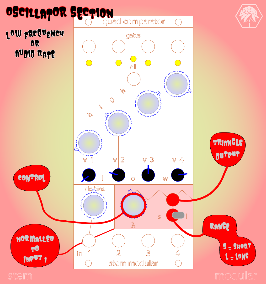
An internal oscillator is normalled to input 1 and allows for the module to be used without any external signals. DC bias shifts the incoming signal higher or lower.
The concept may feel more convoluted than a typical sequencer at first, but it is actually pretty straightforward. Because of its flexibility it can be used to create sequences, pulsewidth audio, distortion, and more depending on how it is configured.
If you’ve made it this far and are interested in learning more, look into our classes (we’ll be posting some new ones soon). Eventually we will be making some window comparator diy projects available, but no idea when at this point. If you have any voltage wisdom to share, please feel free to leave a kind comment.